 |
 |
PPGA to FCPGA | InSTruCtion | |
|
NOTE: This page is an archived copy of a page that was originally located at http://bws.sprintnet.pl/hardware/mainboards/przerobka/r_1stwords.html The original english page no longer exists. I am not the original author. This article is reproduced here with permission from the original author, Fachman I used the information from this page to do my Abit BM6 Celeron II 1.1GHz Coppermine 128 processor upgrade |
|
||||||||||||
|
| |||
|
| |||
|
InSTruCtion | |||
|
| |||
|
"Do you want to save your money?" I do. That`s why last year i have bought the cheapest of the all ABIT`s mainboards - ZM6 based on the INTEL ZX chipset. It is Socket370 board designed to use only Celeron PPGA (Mendocino core) processors. Before i bought it i have checked it`s performance. It has turned out that it is the same as other ABIT`s mainboard - BH6 rev.1.01. I have started to calculate the prices and i have decided it would be better to my budget to save some money. At first, because mainboard itself was cheaper than BH6. At second, because i didn`t have to buy SLOT1-SOCKET370 converter card. I was aware of the fact, that SLOT1 is far more universal, because you can use both SLOT1 and SOCKET370 processors, but i have also knowed that INTEL is planning to fully convert to only SOCKET processors. Now when this time has become the reality and most of the new PENTIUM 3, as well based on the same core - CELERON 2 processors are in SOCKET370 version, INTEL decided to add some troubles for people who thanked similar to me. Now, when i would like to buy the new FCPGA processor, i had two choices - to buy the new mainboard/converter (NEO) or to find the other way. In this article i will show you how to convert your PPGA mainboard to universal one. Before you will use it for your mainboard, if you aren`t sure, first check is it really doesn`t support PENTIUM 3 or CELERON 2 processors. Maybe this instruction won`t be neccessary. This instruction was created for ABIT ZM6 maniboards, but can be used for others as well. The steps are the same. If the mainboard isn`t ready for FCPGA processors none of the bios modifications wont help you. It is the matter of electrical connection. If some manufacturer will write in it`s new bios modifications list, that this version supports Pentium 3 or Celeron 2 (as it happens for ABIT ZM6 bios), it doesn`t mean you wont have to do this modification. It means only that this bios is able to recognize correctly the processor type. Without this modification ABIT ZM6, as well as other PPGA only mainboards wont boot with FCPGA processors. WARNING !! It seems that new series of CELERON 2 which is also FCPGA proccessor doesn`t require this modification to work properly on PPGA mainboards. I have now confirmed information about ABIT ZM6. I don`t know how about other motherboards. As for the PENTIUM 3, it still, even the latest steppings (versions), require this modification on every mainboard. In other case you would see only the black screen. At first i must say that i was inspired by the great article on Tom`s Hardware Guide - FC-PGA Pentium III on Celeron PGA370/Slot1 Converter Cards . It is recommended to read it first. Tom Pabst has made a lot of work to give you the very detailed
theory about the differencies beetween PPGA and FCPGA processors, that`s
why i will only summarize his findings. Basically the PPGA and FCPGA are
different in only few pins. Here is the table of them: 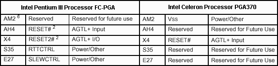 Pins: S35 (RTTCTRL) and E27 (SLEWCTRL) doesn`t interest us, because processors are working not matter is there a high or low signal on them. Here is the picture showing where you can find the three pins
which interest us. If you will have problems identyfing them on the real
socket, please look closer at the cutted corners and where i put the
needle in one of the next pictures (pin AM2). 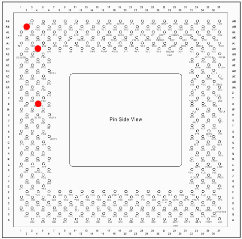 At first put off your processor from the socket. Pins: AH4
(RESET#) and X4 (RESET2#) must be connected together. Use for this a small
piece of cable and soldering iron. On the following pictures you will see
an effect of this operation. The first is the close look: 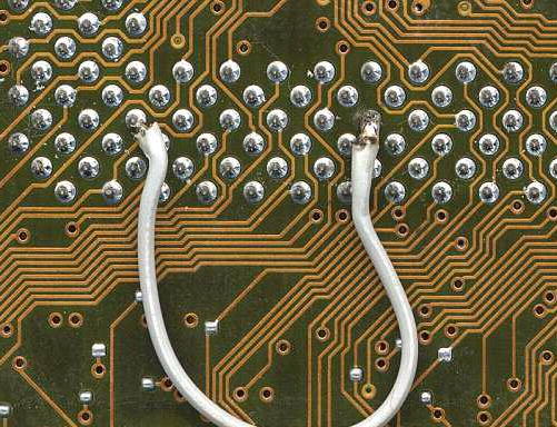 The second is an overview: 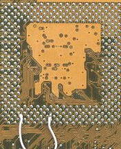 So now we have the RESET signal active. What is left is pin AM2.
On PPGA mainbords it is connected to the ground. In this condition the
FCPGA processor wont boot. The solution is simple. We must disconnect it.
Tom Pabst suggested removing the pin from the processor, but for me this
was unacceptable option, because we wouldn`t be able to respect the
guarranty, if something would happen to processor in the future. I thought
- if we can`t remove the pin from the processor, we must do it from the
socket. Take a look at the SOCKET370 picture: 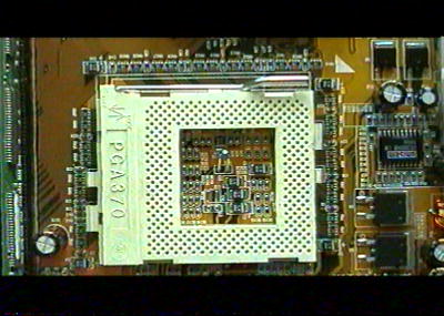 It is the normal, typical closed socket. First you must raise
the lever to the end: 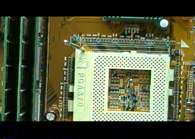 Then you must use the screwdriver to lift up the upper cover of
the socket. Please remember that this is the delicate plastic. Do not use
the strenght more than neccessary. 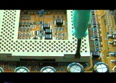 After using the screwdriver, the cover should be removed from
the latch: 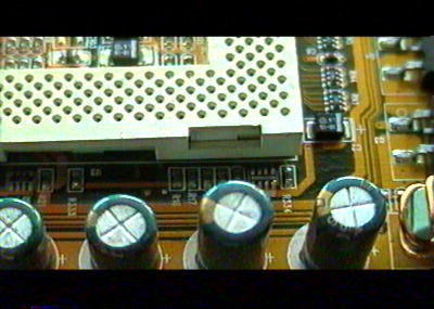 Now completelly remove the cover and take a look what you should
see: 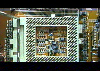 Get the needle and use it to remove the AM2 metal pin from the
socket: 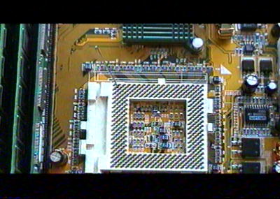 THIS IS THE VERY DELICATE AND TIME CONSUMING OPERATION. I HAVE LOST ABOUT HALF OF AN HOUR TO REMOVE THE PIN FROM THE SOCKET. The pins are very small and you must be very carefull to don`t harm the others, because that would mean the mainboard`s failure. To remove the pin i have moved the needle from the right to the left until the pin would broke. This was the only way i can do it. At first i have tried to use also the soldering iron, but it wont work. After you will remove the pin (it doesnt have to be completelly,
it would be neccessary that processor`s pin wont have the contact with the
socket`s one) put back the cover on the socket: That`s all. Your mainboard is ready for FCPGA processors, but it doesnt mean it won`t work with PPGA also. My old CELERON 366 overclocked to 550MHz worked as usual. I have also tested PENTIUM 3 550E (Coppermine) and CELERON 2 533A (Coppermine) and they all worked fine in normal and overclocked conditions. The disadvantage of this whole operation is possible lost of guarranty. Also to work with FCPGA processors your mainboard must be able
to give 1,5V (1,65V for P3) to the processor and support voltage tweaking
(only for overclocking purposes). If it won`t be able to do this, your
processor will get full 2V, which might be dangerous to your processor.
Althought according to INTEL documentation Coppermine core is able to
operate up to 2,1V, such voltage would generate a lot of heat and if you
don`t have REALLY GOOD cooling the processor might simply burn. In case of
ABIT ZM6 the mainboard properly detects and give it 1,5V(1,65V). You can
also tweak this voltage up to 1,65V (for Celeron 2). Why not more? Well,
there is a bug in ZM6`s bios. To set 1,7V or anything higher you must
first set 1,65V and then after restart set it again to 1,7V. The problemm
is that when you turn the computer off, after next turning on you will
still have 1,5V (according to Voltage meters in CHIPSET SETTINGS MENU).
ABIT ZM6 normally lets you to tweak the voltage in range up to 15%. To
have higher range of Voltage you must first set highest available voltage
(in case of CELERON 2 it would be 1,7V) in SOFT MENU and then reflash the
bios, but with /cc switch. For example: awdflash zm6_qu.bin /cc Now after reflash the new default voltage will be our 1,7V and that mean we will be able to tweak it up to 15% more (up to 1,9V). On other ABITs mainboard this volage tweaking may work also (but not on all). You can use this instruction for converting SLOT1-SOCKET370 converter cards as well. WARNING !! This instruction was created for people, who knows how to use soldering iron and have at least the basic knowledge of electronic. I will not take any responsibility of any damage or anything else that may occur, if you will use this instruction. | |||
|
|
|
Copyright © 2000 [Fachman] |
| | InSTruCtion
|
|